Current Electricity
- Electrical Conductivity: It is the inverse of specific resistance for a conductor whereas the specific resistance is the resistance of unit cube of the material of the conductor.
Where is the conductivity and is resistivity. - SI Unit of Conductivity: The SI unit of conductivity is mhom-1.
- Current through a given area of a conductor: It is the net charge passing per unit time through the area.
- Current Density Vector: The current density vector gives current per unit area flowing through area when it is held normal to the direction of charge flow. Note that the direction of is in the direction of current flow.
- Current Density: Current density j gives the amount of charge flowing per second per unit area normal to the flow.
where n is the number density (number per unit volume) of charge carriers each of charge q and is the drift velocity of the charge carriers. For electrons q = –e. If j is normal to a cross – sectional area A and is constant over the area, the magnitude of the current I through the area is - Mobility: Mobility is defined to be the magnitude of drift velocity per unit electric field.
Now, where q is the electric charge of the current carrier and is its mass.
Thus, mobility is a measure of the response of a charge carrier to a given external electric field. - Resistivity: Resistivity is defined to be reciprocal of conductivity.
It is measured in ohm-meter()
- Resistivity as a function of temperature: It is given as,
Where, is the temperature coefficient of resistivity and is the resistivity of the material at temperature T. - Ranges of Resistivity:
a) Metals have low resistivity: Range of varies from 10–8 Ω m to 10–6 Ω m.
b) Insulators like glass and rubber have high resistivity: Range of varies from 1022 to 1024 times greater than that of metals.
c) Semiconductors like Si and Ge lie roughly in the middle range of resistivity on a logarithmic scale. - Total resistance in Series and in Parallel:
(a) Total resistance R of n resistors connected in series is given by R = R1 + R2 + … + Rn
(b) Total resistance R of n resistors connected in parallel is given by
where is a constant of proportionality called electrical conductivity. This statement is one possible form of Ohm’s law. - If the mass of a charge carrier is large, then for a given field its acceleration will be small and will contribute very little to the electric current.
- Electrical Conductivity: When a conducting substance is brought under the influence of an electric field ,free charges (e.g. free electrons in metals) move under the influence of this field in such a manner, that the current density due to their motion is proportional to the applied electric field.
- Consider a cylindrical material with cross-sectional area A and length L through which a current is passing along the length and normal to the area A, then, since and are in the same direction, Where A is cross-sectional area and L is length of the material through which a current is passing along the length, normal to the area A. But, JA = I, the current through the area A and EL = V1 – V2, the potential difference across the ends of the cylinder denoting V1-V2 as V,Where is called resistance of the material. In this form, Ohm’s law can be stated as a linear relationship between the potential drop across a substance and the current passing through it.
- Measuring resistance: R is measured in ohm (), where
- EMF: Emf (Electromotive force) is the name given to a non-electrostatic agency. Typically, it is a battery, in which a chemical process achieves this task of doing work in driving the positive charge from a low potential to a high potential. The effect of such a source is measured in terms of work done per unit charge in moving a charge once around the circuit. This is denoted by
- Significance of Ohm’s Law: Ohm’s law is obeyed by many substances, but it is not a fundamental law of nature. It fails if
- V depends on I non- linearly. Example is when ρ increases with I (even if the temperature is kept fixed).
- The relation between V and I depends on the sign of V for the same absolute value of V.
- The relation between V and I is non- unique. For e.g., GaAs
An example of (a) & (b)is of a rectifier
- When a source of emf() is connected to an external resistance R, the voltage across R is given by
Where r is the internal resistance of the source.
- Kirchhoff’s First Rule:
At any junction of several circuit elements, the sum of currents entering the junction must be equal the sum of currents leaving it.
In the above junction, current I enters it and currents I1 and I2 leave it. Then, I = I1 + I2.
This is a consequence of charge conservation and assumption that currents are steady, that is no charge piles up at the junction.
- Kirchhoff’s Second Rule:
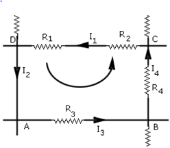
The algebraic sum of changes in potential around any closed resistor loop must be zero. This is based on the principle that electrostatic forces alone cannot do any work in a closed loop, since this work is equal to the potential difference, which is zero, if we start at one point of the loop and come back to it.
This gives: (R1 + R2) I1 + R3 Iv3 + R4 I4 = 0
- In case of current loops:
- Choose any closed loop in the network and designate a direction (in this example counter clockwise) to traverse the loop.
- Go around the loop in the designated direction, adding emf’s and potential differences. An emf is counted as positive when it is traversed (-) to (+) and negative in the opposite case i.e., from (+) to (-). An IR term is counted negative if the resistor is traversed in the same direction of the assumed current, and positive if in the opposite direction.
- Equate the total sum to zero.
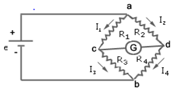
- Wheatstone Bridge: Wheatstone bridge is an arrangement of four resistances R1, R2, R3, R4. The null point condition is given by,

This is also known as the balanced condition. If R1, R2, R3 are known, R4 can be determined. - In a balanced condition of the meter bridge,
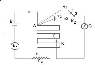
Where is the resistance per unit length of wire and is the length of wire from one end where null point is obtained. - Potentiometer: The potentiometer is a device to compare potential differences. Since the method involves a condition of no current flow, the device can be used to measure potential differences; internal resistance of a cell and compare emf’s of two sources.

i) Potential Gradient: The potential gradient of the wire in a potentiometer depends on the current in the wire.
If an emf is balanced against length , then
Similarly, if is balanced against , then
The comparison of emf’s of the two cells is given by,
.png)

